Detailed Comparison of Anchor Bolt Embedment Length Calculations under Chinese, American and European Codes
Detailed Comparison of Anchor Bolt Embedment Length Calculations under Chinese, American and European Codes
Detailed Comparison of Anchor Bolt Embedment Length Calculations under Chinese, American and European Codes
Anchor Bolt Embedment Length Calculation: Detailed Comparison of YD 5131 / ACI 318 / EN 1992-4
Conclusion First
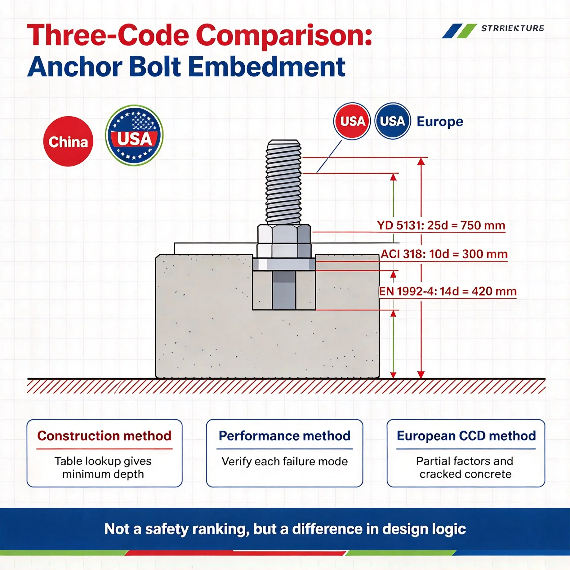
The Chinese code is governed mainly by constructive (prescriptive) embedment lengths (table lookup); the US code focuses on embedment depth (hef); the European code focuses on cracking (cracked / uncracked concrete).
· China: communication-industry-specific code, mainly table lookup, with detailed constructive provisions (YD 5131-2019).
· United States: performance-based design, concrete failure-mode analysis, the CCD method.
· Europe: close to ACI 318, but with an independent partial safety factor system.
I. Chinese Code: YD 5131-2019, Code for Design of Steel Tower and Mast Structures of Mobile Communication Engineering
Basis of the Code
· YD 5131-2019, Code for Design of Steel Tower and Mast Structures of Mobile Communication Engineering, Clause 7.3.7 — the dedicated code for tower and mast structures in the communication industry.
· Clause 7.3.7 of this code specifies the design requirements for anchor bolts; Appendix F provides detailed anchor-bolt parameters and an embedment-length data table. Note: current communication tower foundation design uniformly uses C30 as the minimum grade; C20 is retained only for reference to earlier completed projects.
Key Design Provisions of Clause 7.3.7
The design of anchor bolts shall satisfy the following six requirements:
· Design according to the vertical force, horizontal force and bending moment transmitted from the upper steel tower/mast structure to the tower base; consider installation and construction requirements, and carry out necessary checking for the post-cast concrete layer on top of the foundation.
· The embedment depth of anchor bolts shall be determined in accordance with the anchorage length of a tensioned reinforcing bar; where the embedment depth is restricted, an anchor plate may be added to the bolt.
· The spacing between anchor bolts shall not be less than 4d; the distance from the center of an anchor bolt to the edge of the concrete member shall not be less than the larger of 4d and 100 mm. Where the above requirements cannot be satisfied, measures such as providing transverse constructive reinforcement shall be adopted.
· The design of anchor bolts shall take into account the actual erection-adjustment of the upper steel tower/mast structure and the actual setting errors of the embedded parts of the foundation, and the anchor bolt holes in the tower-column base plate shall be enlarged accordingly.
· A levelling nut shall be provided on the flange at the base of a single-tube tower column. Where a levelling-nut gap is set between the base plate and the foundation top surface, the spacing shall preferably be taken as twice the anchor-bolt diameter.
· After erection, the tower base plate shall fit closely against the concrete bearing surface below and shall not remain suspended for a long period. Where a post-cast concrete layer is provided beneath the tower base plate, the strength and stability of the anchor bolts in the suspended section during the construction stage shall be checked as a beam-column member.
Appendix F: Common Anchor Bolt Data Tables
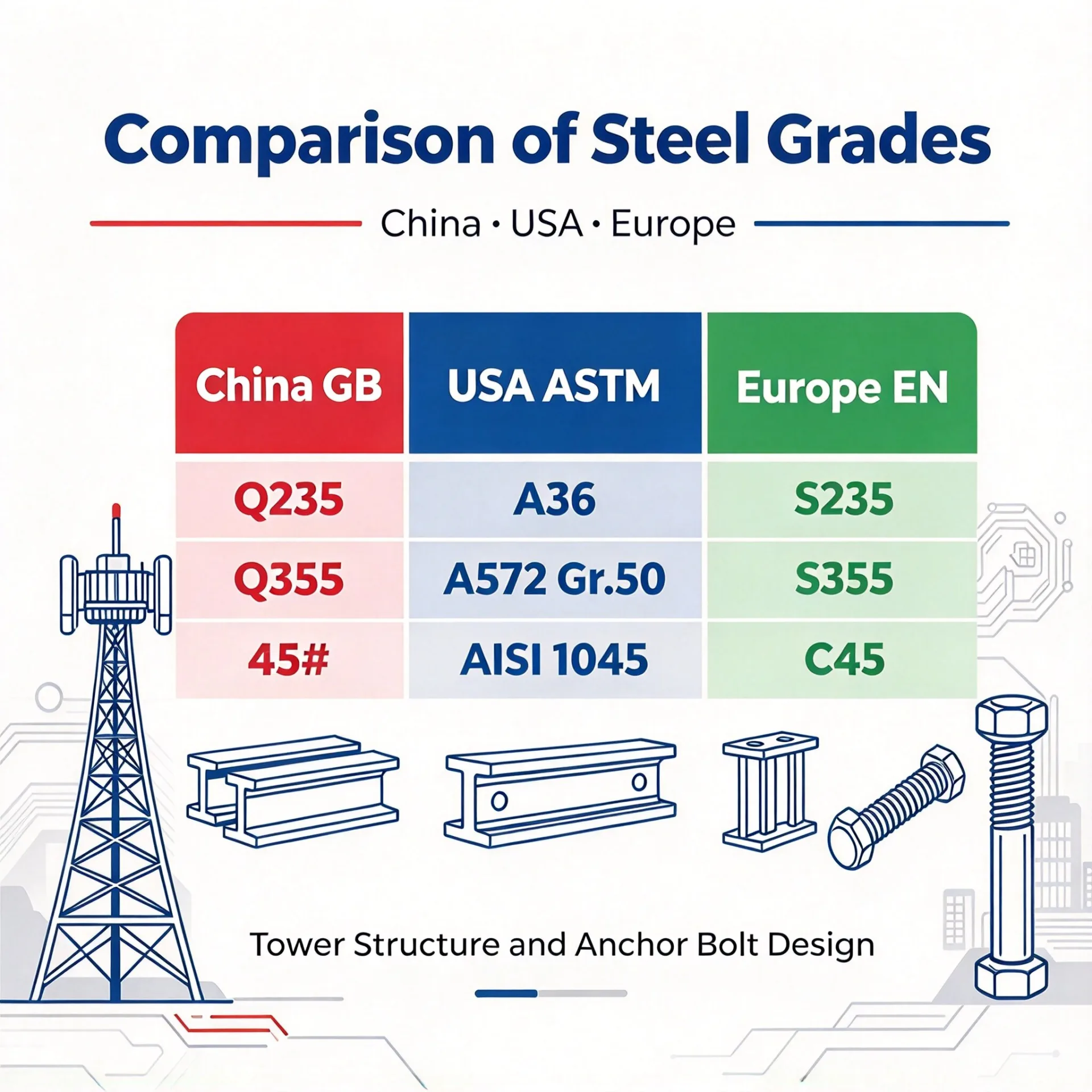
· Table F.0.1, common anchor bolt parameter table: M12~M72, steels Q235/Q345/45#.
· Including: thread pitch p, effective diameter de, effective area Ae, design tensile capacity Nt (Q235/Q345/45#), and double-nut dimensions a/b.
· Anchor bolt types are divided into four kinds:
· Type a: hooked anchor bolt — the most commonly used, end hooked at 90°.
· Type b: anchor bolt with bolted anchor plate — recommended for 45# steel.
· Type c: anchor bolt with welded anchor plate — site welded.
· Type d: anchor bolt with stiffened anchor plate — used for large-diameter anchor bolts.
Table F.0.2, minimum embedment length L1 of Type-a hooked anchor bolts (concrete grades C30~C40; C20 retained only for reference to existing projects; steels Q235/Q345/45#).
V. Practical Engineering Recommendations for Communication Towers
Scenario 1: Chinese project → bidding overseas
First look up the embedment length from YD 5131-2019 tables (e.g. Q345/C30 → 25d = 750 mm for M30). Then back-calculate hef in accordance with ACI 318 or EN 1992-4 and check whether it is satisfied. If the ACI-calculated hef > La, the domestic review can directly approve the constructive value.
Scenario 2: Overseas project → domestic review
US code gives embedment length La,US = 300 mm (hef/d = 10). Look up YD 5131-2019: Q345/C30, M30 → 25d, i.e. 25 × 30 = 750 mm [Source: YD 5131-2019, Table F.0.2].
Conclusion: for this example, the empirical constructive value of YD 5131-2019 (25d = 750 mm) is clearly greater than the ACI result (300 mm) — the two methods differ, and their merits cannot be compared directly.
Scenario 3: European projects
EN 1992-4:2018 is similar to ACI 318 in method and can be compared on an equivalent basis. Note: the European code treats cracked concrete more strictly (post-installed anchor kcr,N = 7.7), and the embedment depth calculated by the European code for the same project is usually larger than that by the US code.
VI. Closing: Three Logics, Three Styles
· Chinese code: the engineer “looks it up in a table and is done” — simple and direct, derived from extensive engineering experience, with conservative factors built into the constructive provisions.
· US code: the engineer “calculates the failure modes” — first identify all possible failure paths, then check each one and take the minimum — rational but complex, requiring software support.
· European code: the engineer “calculates the failure modes but with European partial factors” — the framework is the same as ACI, but the safety factor system is independent and more sensitive to cracked concrete.
Key memory points
· Q235/C30 → 20d; Q345/C30 → 25d (taking M30 as example) [Source: YD 5131-2019, Table F.0.2] (C20 is no longer recommended for new projects).
· hef calculation → ACI 318 (United States).
· CCD + partial factors → EN 1992-4 (Europe).
VII. Unified Worked Example Comparison Across the Three Codes
7.1 Unified Conditions of the Worked Example
· Anchor bolt: M30, Grade 8.8 (ISO 898-1), fuk = 800 MPa, fy = 640 MPa. Note: Q345 (fy ≈ 345 MPa) and Grade 8.8 (fy ≈ 640 MPa) differ in strength; this example uses Grade 8.8 for a unified comparison.
· Effective cross-sectional area: As,e = 706.9 mm² [Source: YD 5131-2019, Table F.0.1, M30].
· Concrete: C30, fc = 14.3 MPa (design value), fck = 30 MPa (characteristic value) [Source: GB 50010-2010, C30].
· Design tensile force: N = 150 kN.
· Edge distance: c/hef = 150/300 = 0.5 (falls in the insufficient-edge-distance region, with significant reduction).
7.2 Chinese Code YD 5131-2019 Worked Example
(1) Constructive table lookup (YD 5131-2019, Appendix F)
· Q345 anchor bolt + C30 concrete → L1 = 25d [Source: YD 5131-2019, Table F.0.2].
· L1 = 25 × 30 = 750 mm [Source: YD 5131-2019, Table F.0.2].
(2) Levelling-nut gap
· Levelling-nut gap = 2d = 60 mm [Source: YD 5131-2019, Clause 7.3.7, item 5].
(3) Spacing requirements
· Anchor-bolt spacing ≥ 4d; center-to-edge distance ≥ max(4d, 100 mm) [Source: YD 5131-2019, Clause 7.3.7, item 3].
Conclusion: YD 5131-2019 is governed by constructive provisions. For M30/Q345/C30 → embedment length 750 mm, levelling-nut gap 60 mm, spacing ≥ 120 mm.
7.3 US Code ACI 318-19 Worked Example
(1) Steel failure check
· Nsa = Ase·futa = 706.9 × 830 ≈ 587 kN [Source: ACI 318-19, Section 17.6.1.2, Eq. (17.6.1.2)].
· Φs = 0.75 [Source: ACI 318-19, Table 17.5.3(c)].
· ΦNsa = 0.75 × 587 ≈ 440 kN [Source: ACI 318-19, Section 17.5.2] > 150 kN ✓
(2) Concrete cone breakout (try hef = 300 mm, i.e. 10d)
· Take kc = 17 (post-installed anchor). Note: for a cast-in headed anchor, ACI 318-19 adopts kc = 24; for J-hook, L-hook or hooked anchor rods, an appropriate kc value shall be determined with reference to manufacturer certification data. This example adopts the post-installed anchor value for demonstration of the calculation procedure.
· ψed,N = 0.7 + 0.3 × 150/(1.5 × 300) = 0.7 + 0.3 × 1/3 = 0.80 [Source: ACI 318-19, Eq. (17.6.2.4.1b)].
· ψc,N [Source: ACI 318-19, Section 17.6.2.5]: cracked concrete ψc,N = 1.0; uncracked concrete ψc,N = 1.25 (cast-in anchor) / 1.4 (only for post-installed adhesive anchors certified to ACI 355.4).
· ΦNcb = 0.65 × 484 × ψed,N × ψc,N × ψcp,N = 0.65 × 484 × 0.80 × 1.0 × 0.667 ≈ 168 kN > 150 kN.
Where: ψed,N = 0.80 (edge-distance reduction) [Source: ACI 318-19, Eq. (17.6.2.4.1b)]; ψc,N = 1.0 (cracked concrete) [Source: ACI 318-19, Section 17.6.2.5]; ψcp,N = 0.667 (cracked + insufficient edge distance) [Source: ACI 318-19, Section 17.6.2.6, Eq. (17.6.2.6.1)]: ψcp,N = 0.5 + ca,min/(3 × hef) = 0.5 + 150/(3 × 300) = 0.667.
7.4 European Code EN 1992-4:2018 Worked Example
(1) Steel failure check
· NRd,s = As × fuk/γMs, where the steel characteristic resistance NRk,s is given in Section 7.2.1.3 and the design value is calculated by Eq. (4.3) [Source: EN 1992-4:2018, Section 7.2.1.3 and Eq. (4.3)].
· γMs: determined by the ETA or NDP (common reference values: 1.2~1.25 normal / 1.0~1.15 seismic) [Source: EN 1992-4:2018, Section 4.4.2; the standard gives no specific value].
(2) Concrete cone breakout (hef = 300 mm, cracked concrete)
· NRk,c = NRk,c0 × (Ac,N / Ac,N0) × ψs,N × ψre,N × ψec,N [Source: EN 1992-4:2018, Section 7.2.1.4, Eq. (7.1)].
· Where: NRk,c0 = k1 × √fck × hef^1.5 (basic characteristic resistance); Ac,N/Ac,N0 (projected-area reduction); ψs,N (edge-distance reduction); ψre,N (reinforcement influence); ψec,N (eccentricity influence) [Source: EN 1992-4:2018, Section 7.2.1.4].
· γMc: determined by the ETA or NDP (common reference value ≈ 2.16 for cracked concrete) [Source: EN 1992-4:2018, Section 4.4.2].
Conclusion: under EN 1992-4 with cracked concrete (post-installed anchor k1 = 7.7), 10d (300 mm) provides only about 101 kN capacity, which does not satisfy the 150 kN design requirement.
Back-calculate the embedment depth required for 150 kN: from NRk,c / hef^1.5, 101 kN / 300^1.5 = 150 kN / hef,new^1.5, giving hef,new = 300 × (150/101)^(2/3) ≈ 392 mm; considering a safety margin, take 420 mm (14d) [Source: back-calculation from EN 1992-4:2018, Eq. (7.2)].
7.5 Comparison Summary of the Three Codes
|
Code |
Design Method |
Minimum Embedment for 150 kN |
Features |
|
YD 5131-2019 |
Constructive table lookup |
750 mm (25d) |
Mandatory constructive rule for domestic communication towers, built-in safety margin |
|
ACI 318-19 |
CCD performance limit state |
300 mm (10d) |
Checks failure modes item by item; edge-distance deficiency is reduced |
|
EN 1992-4 |
CCD + European partial factors |
420 mm (14d, cracked concrete) |
Strict for cracked concrete; relies on product ETA certification |
Table 1 Comparison summary of the three codes
Engineering recommendation: for domestic projects, design in accordance with the Chinese constructive requirements (25d = 750 mm for M30 Q345/C30); for overseas projects, design by the performance-based method of ACI 318 or EN 1992-4, but convert to the Chinese constructive value for the domestic review.
Cross-Code Comparison: Empirical Construction vs Performance Calculation
Why is the hef calculated by ACI (300 mm) far smaller than the empirical Chinese value (750 mm)? The logic of the two systems is fundamentally different:
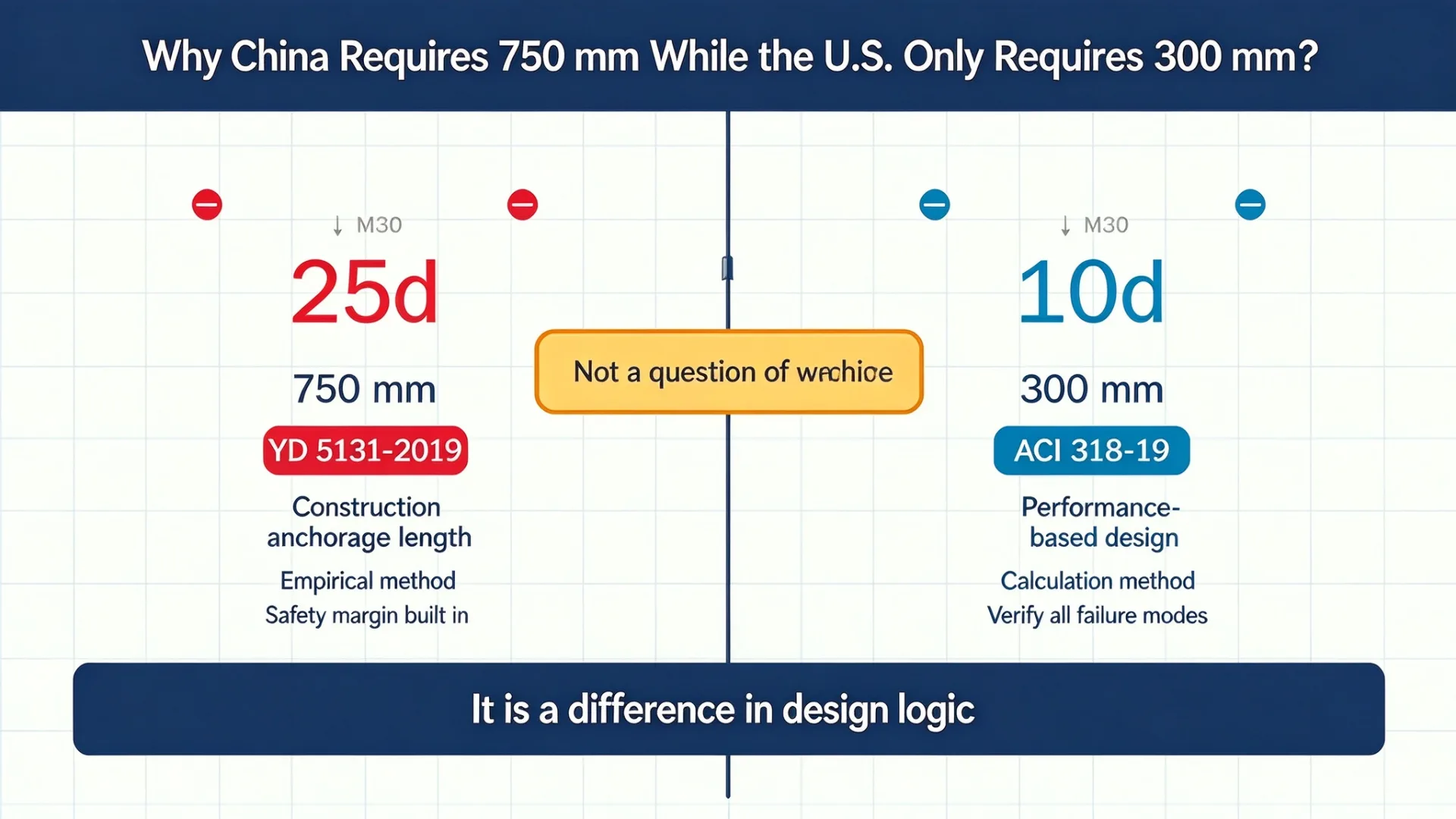
· Essential difference:
· The Chinese code tells you “how deep is deep enough” (an empirical conclusion).
· The US code tells you “how to calculate how deep is enough” (a calculation method).
The different results do not mean that one is more conservative or safer than the other — they simply answer different questions.
The Chinese code provides an “empirical answer”, while the European and American codes provide a “solution process”. The two are not a contest of right or wrong, but a difference in engineering philosophy.